An Electric Gate Valve controls fluid flow by lifting or lowering a solid gate inside the valve body. Unlike a manual handwheel, its electric actuator converts motor rotation into precise stem movement. The gate travels vertically, leaving the pipeline fully open or tightly closed. It is not designed for frequent throttling. That distinction matters.
The International Energy Agency reports that electric motor systems consume more than half of global electricity. This places efficiency, control, and maintenance under growing industrial scrutiny. The U.S. Department of Energy also identifies motor-driven equipment as a major share of industrial electricity use. In practical terms, an inefficient actuator can waste energy every time a valve cycles. Small losses become expensive across hundreds of operating cycles.
Industry standards provide a safer technical foundation. API 600 addresses steel gate valves, while ASME B16.34 covers pressure-temperature ratings and valve construction. ISO 5210 supports actuator attachment and interface requirements. These references help engineers select suitable equipment for water treatment, power generation, oil and gas, and process plants. Yet standards do not remove every risk. Installation errors still happen.
A typical system includes the valve body, gate, stem, electric actuator, limit switches, and control wiring. When a signal arrives, the actuator drives the stem until a preset limit is reached. Torque protection can stop movement when resistance becomes abnormal. The sound may change. The actuator may also overheat.
This article explains how an Electric Gate Valve works, where it performs well, and where its limitations deserve honest attention. Some applications appear simple, but real service conditions often disagree.
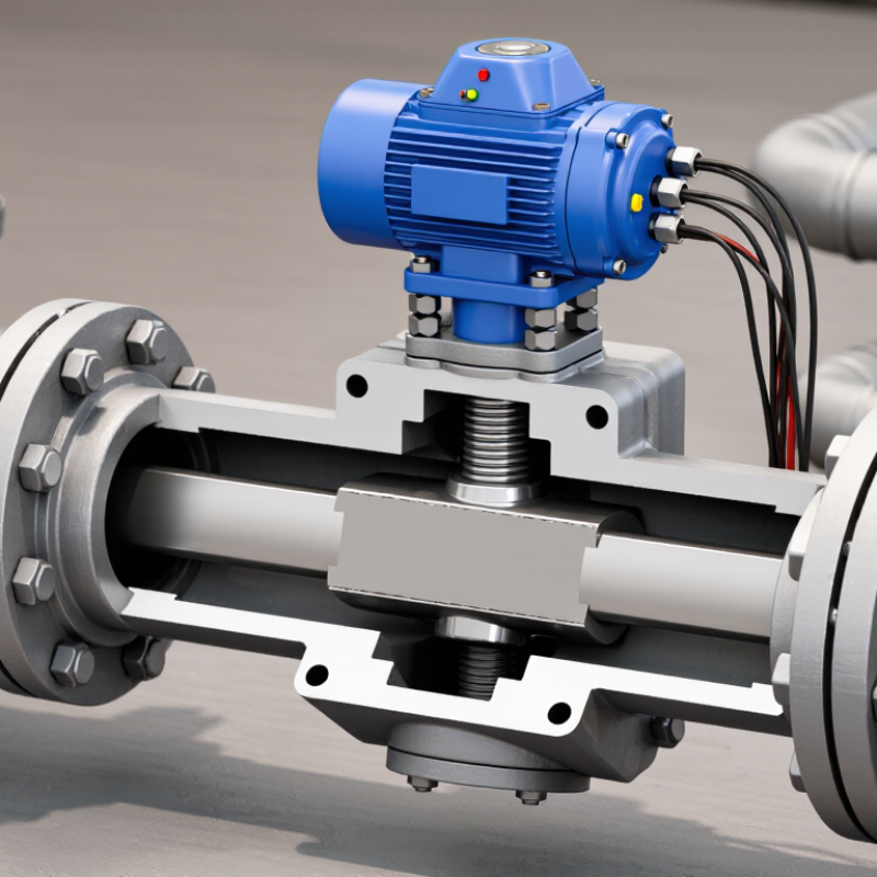
An electric gate valve is an isolation device operated by an electric actuator. Its core purpose is simple: stop or permit fluid flow through a pipeline. When energized, the motor rotates a stem. The stem moves a wedge or slab gate vertically across the passage. A fully raised gate leaves a nearly unobstructed flow path. A fully lowered gate closes the line.
It is not normally a throttling valve. Partial opening can create turbulence, vibration, and seat damage. This distinction matters in water treatment, power generation, and process facilities. The UN World Water Development Report 2024 states that agriculture accounts for about 70% of global freshwater withdrawals. Reliable isolation therefore supports safer maintenance and controlled water distribution. The IEA’s Energy Efficiency 2023 report also identifies industry as responsible for roughly 37% of global final energy consumption. Reducing leakage and avoiding unnecessary pumping remain practical priorities.
An actuator may include limit switches, torque protection, and position feedback. These features help operators confirm whether the gate is open or closed from a control room. Proper sizing requires attention to valve pressure class, stem load, cycle frequency, and power supply. Standards such as ISO 5210 help define actuator attachment and output requirements. Field experience shows that installation errors still occur, especially when flow direction and travel limits receive little attention. Remote operation is useful, but it does not replace inspection. A valve can report “closed” while debris prevents tight sealing. That uncomfortable possibility deserves routine testing.

An electric gate valve uses an electric actuator to open or close a linear flow passage. Its body contains the gate, seats, bonnet, and stem. The gate moves vertically, rather than rotating like a ball valve. When fully raised, it creates a relatively open passage. When lowered, it presses against the seats and stops flow.
The actuator is the working power source. Its motor produces rotation, while a gearbox converts that rotation into controlled stem movement. Limit switches stop travel at the open and closed positions. Torque switches protect the stem and gate when debris increases resistance. A control board receives signals from a remote system or local panel. Position feedback then confirms whether the valve is open, closed, or somewhere between. It sounds simple. It is not always simple.
Seals around the stem and bonnet help prevent external leakage. The valve body handles pressure, while the seats provide internal shutoff. Engineers must match actuator torque with pressure, temperature, cycle frequency, and gate size.
The U.S. Department of Energy’s 2022 Industrial Decarbonization Roadmap notes that motor-driven systems consume about 23% of U.S. electricity. Efficient actuator sizing therefore matters beyond valve operation.
In field inspections, incorrect limit-switch settings remain a practical concern. A valve may indicate “closed” while the gate is not fully seated. That small error deserves serious attention.
An electric gate valve controls flow by lifting or lowering a metal gate inside the pipeline. It is designed for isolation, not precise throttling. The operation begins when a control system sends an open or close signal. The electric motor then converts electrical energy into rotary motion. A gearbox reduces speed and increases torque. This torque turns the valve stem.
The stem moves the gate vertically through threaded motion. As the gate reaches its end position, limit switches stop the motor. A torque switch can also interrupt power when resistance becomes excessive. This protects the stem, gearbox, and seating surfaces. During closing, the gate presses against the seat and blocks the passage. During opening, it rises fully above the flow path. The U.S. Department of Energy’s Motor Systems Market Assessment reports that motor-driven systems consume about 68% of industrial electricity in the United States. This figure explains why actuator sizing and efficient operation deserve attention, even though a valve motor is relatively small. The sequence sounds tidy. Real systems are less obedient.
Tips: Confirm the pipe pressure, temperature, voltage, torque, and cycle frequency before selection. IEC 60534 and ISO 5211 provide useful engineering references for valve and actuator interfaces. Never treat a gate valve as a control valve. Partial opening may cause vibration, seat damage, and unstable flow. In field work, check limit-switch settings manually. A small calibration error can leave the gate apparently closed but not fully sealed.
| Step | Operating Stage | What Happens | Valve Position | Main Components Involved | Operational Result |
|---|---|---|---|---|---|
| 1 | Control Signal | An electrical command is sent from a switch, control panel, automation system, or remote controller. | Unchanged | Control circuit, wiring, controller, position command | The actuator receives an open or close instruction. |
| 2 | Motor Energizing | The electric motor starts and produces rotary motion. The actuator may use gears to increase torque and reduce speed. | Begins moving | Electric motor, gearbox, coupling, actuator housing | Rotary motor movement is converted into controlled valve movement. |
| 3 | Stem Movement | A threaded stem moves the gate vertically. In a rising-stem design, the stem visibly travels upward or downward; in a non-rising design, it rotates without noticeable vertical travel. | Opening or closing progressively | Stem, stem nut, yoke, thrust mechanism | The gate moves away from or toward the flow passage. |
| 4 | Gate Disengagement | During opening, the gate lifts clear of the seats, creating a nearly straight flow path with relatively low pressure loss. | Partially open to fully open | Gate, body, bonnet, valve seats | Fluid flow increases as the gate clears the passage. |
| 5 | Open Limit Detection | A limit switch, position sensor, or actuator control circuit detects that the gate has reached the selected open position. | Fully open | Limit switches, position indicator, control module | Power to the motor is interrupted, preventing unnecessary travel. |
| 6 | Closing Command | A close signal reverses the motor direction. The gearbox drives the stem so the gate travels downward toward the seats. | Fully open to partially closed | Motor, gearbox, stem, gate | The flow passage becomes progressively restricted. |
| 7 | Seat Contact | The gate contacts the valve seats. The actuator supplies the required closing thrust or torque to achieve shutoff, subject to the valve design and service conditions. | Nearly closed to closed | Gate, seats, stem, thrust assembly | Flow is stopped when the gate reaches its fully seated position. |
| 8 | Closed Limit Detection | The closed-position limit switch or sensor confirms that the gate has completed its travel. | Fully closed | Limit switch, position indicator, motor control circuit | The motor stops and the control system receives the closed-status signal. |
| 9 | Status Monitoring | The actuator or control system can report position, motor status, travel limits, overload conditions, and faults when these functions are installed. | Open, closed, or intermediate | Feedback switches, sensors, control panel, alarm circuit | Operators can verify valve status and identify abnormal operation. |
What Is an Electric Gate Valve and How Does It Work?
An electric gate valve uses a motorized actuator to raise or lower a gate inside a pipeline. Its main purpose is isolation, not precise flow throttling. Control may come from local pushbuttons, a PLC, or a remote supervisory system. Open and close commands travel through wired signals, fieldbus networks, or industrial Ethernet. Position feedback then confirms whether the gate has fully moved.
Control quality depends on the actuator’s power source. Common options include single-phase or three-phase AC supplies, low-voltage DC systems, and battery-backed units. An uninterruptible power supply can preserve communication during short outages. The International Energy Agency reports that electric motor systems consume about 50% of global electricity. That figure makes efficient actuator sizing important, even though a valve motor usually runs briefly. Oversized motors waste energy and may increase closing torque.
Safety features should include torque limiting, travel limit switches, emergency shutdown logic, and mechanical position indicators. A manual override helps operators respond when power or control signals disappear. Interlocks can prevent movement while downstream equipment remains pressurized. IEC 60204-1 supports safe electrical equipment design, while IEC 61508 addresses functional safety principles. Cybersecurity also matters when valves connect to networks; NIST SP 800-82 recommends separating control systems from less trusted networks. One weakness is often overlooked: a perfect control diagram cannot compensate for poor commissioning. Dirt, incorrect limit settings, or a failed feedback switch can leave a valve appearing closed when it is not. That deserves a physical check.
What Is an Electric Gate Valve and How Does It Work?
An electric gate valve uses a motorized actuator to move a gate inside the valve body. When the actuator turns, the stem raises or lowers the gate. The gate fully opens or blocks the fluid passage. This design suits systems that need reliable isolation rather than precise flow control. Electric signals can operate the valve from a control panel or automated system. Some installations also include position feedback and manual override features. The movement is usually steady and controlled.
Common Applications, Benefits, and Limitations
Electric gate valves appear in water treatment plants, irrigation networks, HVAC systems, and industrial process lines. They work well on large pipelines where manual operation would be slow or physically difficult. Remote operation improves worker safety around hot, pressurized, or restricted areas. Their full-bore passage can reduce pressure loss when completely open. They also support scheduled operation and basic process automation. That saves time.
However, an electric gate valve is not ideal for frequent throttling. Partial opening may cause vibration, seat wear, and unstable flow. Power failure can stop the actuator unless a backup system is installed. Moisture, dust, and incorrect wiring may also cause operating faults. In field inspections, technicians should check torque settings, limit switches, stem condition, and enclosure sealing. A common mistake is selecting a valve by pipe size alone. Fluid pressure, temperature, cycle frequency, and emergency requirements matter too. The “maintenance-free” assumption often needs reconsideration.
A&B has become the leader in fresh packing and cleaning equipment for fruits and vegetables worldwide. We have achieved this by relentlessly working to produce new and innovative ideas, along with the best customer service on Earth combined with hard working, dedicated, loyal employees and the latest industrial manufacturing techniques. We are now proud to say that we manufacture The Fulcrum Fresh Harvester, this is a one of a kind Berry Harvester that was specifically designed to handle fresh pick blueberries.
732 W. Saint Joseph Street
Lawrence, MI 49064
Phone: 269-539-4700 Fax: 269-539-4705
sale@industrialpackagingmachines.com